- 您现在的位置:买卖IC网 > Sheet目录320 > DC1724A (Linear Technology)BOARD EVAL LTM8029
�� �
�
�DEMO� MANUAL� DC1724A�
�PERFORMANCE� SUMMARY�
�(T� A� =� 25°C)�
�PARAMETER�
�Input� Voltage� Range�
�Output� Voltage�
�Maximum� Output� Current�
�Typical� Switching� Frequency�
�Typical� Efficiency�
�0�
�–20�
�–40�
�–60�
�–80�
�–100�
�–120�
�CONDITIONS�
�V� OUT� =� 5V�
�V� IN� =� 12V,� V� OUT� =� 5V,� I� OUT� =� 600mA�
�VALUE�
�5.6V� to� 36V�
�5V�
�600mA�
�600kHz�
�85%�
�–140�
�0�
�0.5�
�1�
�1.5�
�2�
�2.5�
�3�
�3.5�
�4�
�4.5�
�5�
�FREQUENCY� (MHz)�
�DC1724A� F01�
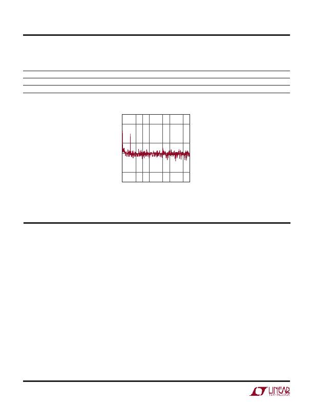
�Figure� 1.� DC1724A� Output� Noise� Spectrum�
�(V� IN� =� 12V,� V� OUT� =� 5V,� I� OUT� =� 600mA)�
�QUICK� START� PROCEDURE�
�DC1724A� provides� an� easy� way� to� evaluate� the� performance�
�of� the� LTM8029.� Refer� to� Figure� 2� for� proper� measurement�
�equipment� setup� and� follow� the� procedure� below:�
�NOTE:� When� measuring� the� input� or� output� voltage� ripple,�
�care� must� be� taken� to� avoid� a� long� ground� lead� on� the�
�oscilloscope� probe.� Measure� the� input� or� output� voltage�
�ripple� by� touching� the� probe� tip� directly� across� the� V� IN� or�
�V� OUT� and� GND� terminals.� See� Figure� 3� for� proper� scope�
�probe� technique.�
�1.� Place� JP1� on� the� ON� position.�
�2.� With� power� off,� connect� the� input� power� supply� to� V� IN�
�and� GND.�
�3.� Turn� on� the� power� at� the� input.�
�NOTE:� Make� sure� that� the� input� voltage� does� not� exceed�
�36V.�
�4.� Check� for� the� proper� output� voltage.�
�NOTE.� If� there� is� no� output,� temporarily� disconnect� the�
�load� to� make� sure� that� the� load� is� not� set� too� high� or�
�is� shorted.�
�5.� Once� the� proper� output� voltage� is� established,� adjust�
�the� load� within� the� operating� range� and� observe� the�
�output� voltage� regulation,� ripple� voltage,� efficiency� and�
�other� parameters.�
�dc1724af�
�2�
�发布紧急采购,3分钟左右您将得到回复。
相关PDF资料
DCATV
SURGE SUPPRESSOR F COAX
DD1P030MA1
CONN PLUG 30POS 0.5MM
DD2P040MA1
CONN PLUG 40POS 0.5MM
DEIC421
RF MOSFET DRIVER 20 AMP
DEMO56F8013-EE
BOARD DEMO FOR 56F8013
DEMO908QC16
BOARD DEMO FOR MC908QC16
DEMO9RS08KA8
BOARD DEMO FOR MC9RS08KA8
DEMO9RS08KB12
DEMO BOARD FOR 9RS08KA12
相关代理商/技术参数
DC1725A
制造商:Linear Technology 功能描述:EVAL BOARD, LT3759 BOOST CONVERTER, Silicon Manufacturer:Linear Technology, Sili 制造商:Linear Technology 功能描述:EVAL BOARD, LT3759 BOOST CONVERTER, Silicon Manufacturer:Linear Technology, Silicon Core Number:LT3759, Kit Application Type:Power Management - Voltage Regulator, Application Sub Type:Boost Converter, Kit Contents:Eval Board LT3759 , RoHS Compliant: NA
DC-1727
制造商:INTRONICS 制造商全称:INTRONICS 功能描述:15 Watt Single & Dual Output DC-DC Converters
DC-1728
制造商:INTRONICS 制造商全称:INTRONICS 功能描述:15 Watt Single & Dual Output DC-DC Converters
DC-1729
制造商:INTRONICS 制造商全称:INTRONICS 功能描述:15 Watt Single & Dual Output DC-DC Converters
DC172AT
制造商:Hewlett Packard Co 功能描述:HP USB Optical Scroll Mouse - Mouse - optical - 3 button(s) - wired - USB - Smar 制造商:Hewlett Packard Co 功能描述:SMART BUY 2BTN USB OPTICAL
DC1730A
制造商:Linear Technology 功能描述:EVAL BOARD, LT3973 STEP DOWN REGULATOR, Silicon Manufacturer:Linear Technology,
DC-1731
制造商:INTRONICS 制造商全称:INTRONICS 功能描述:15 Watt Single & Dual Output DC-DC Converters
DC-1732
制造商:INTRONICS 制造商全称:INTRONICS 功能描述:15 Watt Single & Dual Output DC-DC Converters